-If you’re just here for the Google Sheet and don’t want to read the page, click here.-
I’m in the process of converting my dad’s ATV to electric drive, as one does, and trying to decide how to build the battery pack. I know that I want at least 40 miles of range, which I’m estimating to require about 8kWh of capacity. And since I didn’t want this to be a lame golf-cart-like underpowered wonder, I bought a 60hp motor (the Motenergy ME1507). So the battery needs to be able to output about 600 amps for a few seconds, and around 150 amps continuous, at 72 volts. But due to space, weight, and cost constraints, I don’t think it’s practical to put a proper thermal management system on the pack to keep it cool, so that means I need to use cells that don’t get too warm during normal use.
I first had to decide what form factor of cells would be best, but that was a pretty easy decision, as I’m dealing with a pretty tiny and odd-shaped space where the battery has to fit.
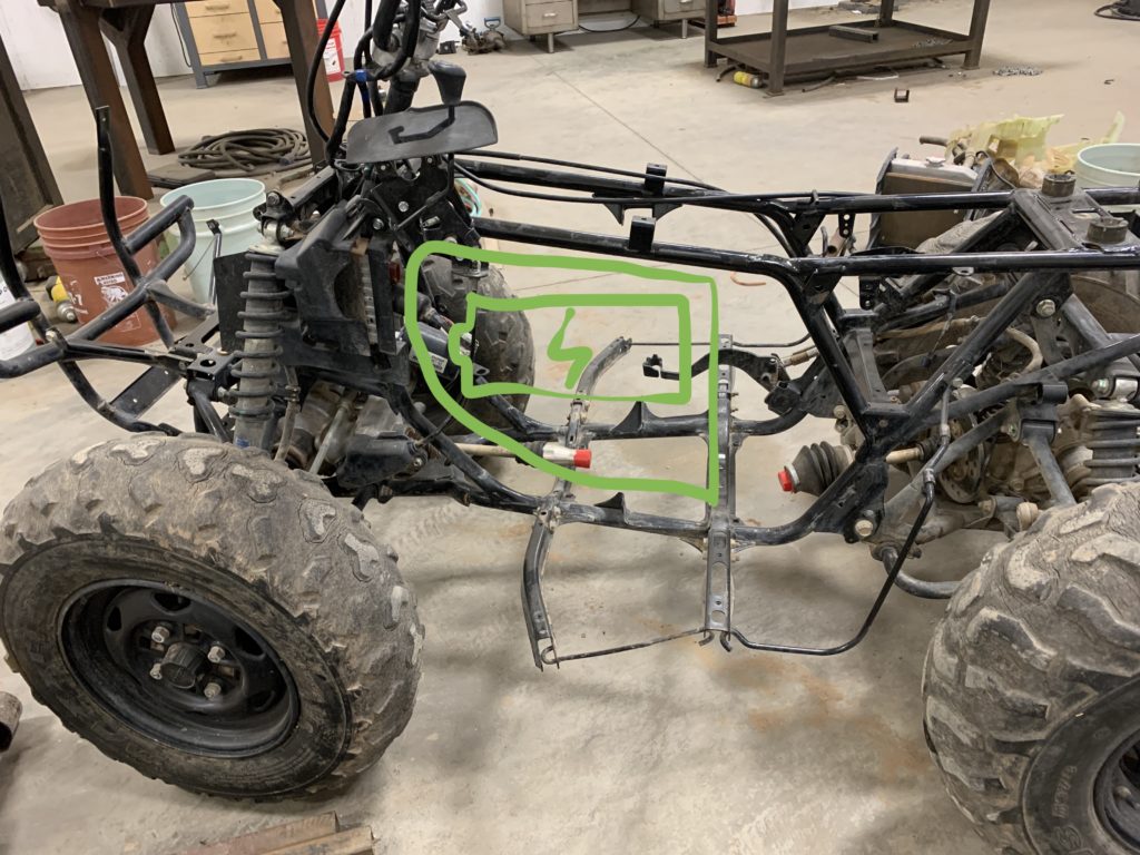
To fit the maximum energy capacity in this odd-shaped space, small cells offer the most flexibility. Also, using small cells means there will be a lot of them, which can be a good thing, because if one cell fails it doesn’t dramatically affect the performance of the pack. So I decided to use small cylindrical cells, either 18650s or 21700s, like those found in old-fashioned laptops and modern cordless drills.
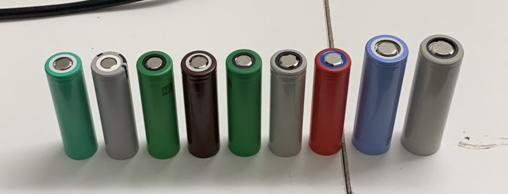
I need a good balance of energy density & power density, in a cell that stays cool. I didn’t find enough info online to know which cells would be appropriate, so I bought a bunch of cells to test them myself.
To test the cells, I needed a way to discharge them at a constant rate, without accidentally discharging them too much. I also needed a safe and controlled way to charge the cells during testing. For that, I bought the ZKE Tech EBC-A20. This can charge cells at up to 5 amps, and discharge them at up to 20 amps.

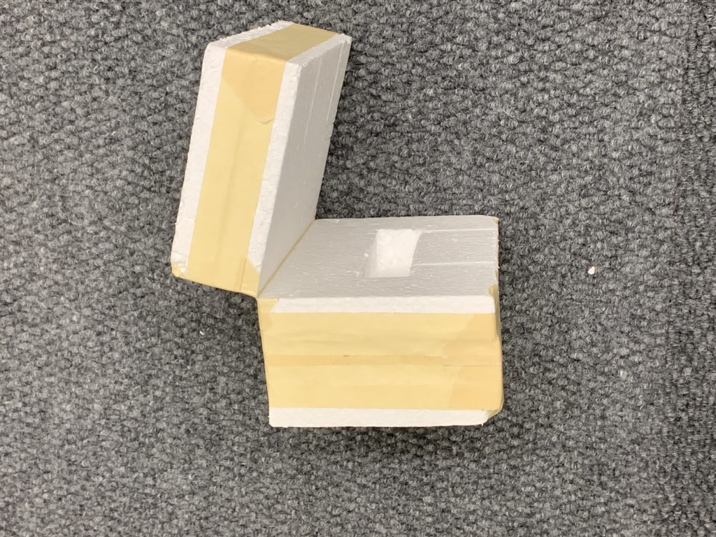
To simulate the cells being inside of a battery pack, I enclosed them in an insulated box made of Styrofoam.
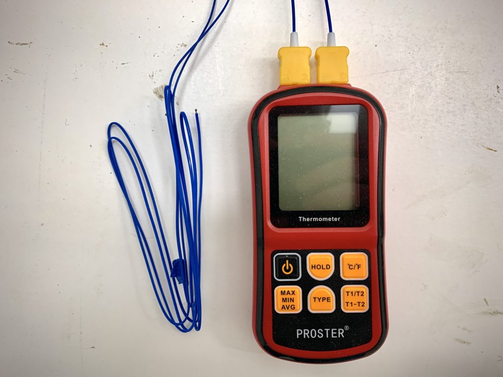
And finally, to monitor the temperature as I charged & discharged the cells, I used this Proster dual-channel thermometer.
For more details on the testing equipment and procedures, see the Google Sheet. I tried to do this in a controlled, well-documented manner so others can replicate my tests in the future. Below is a photo of the entire testing setup. I used an old phone to record a time-lapse of the load tester and thermometer so I have all the data in one place. The second phone just has cell info so I have that in the time-lapse as well.
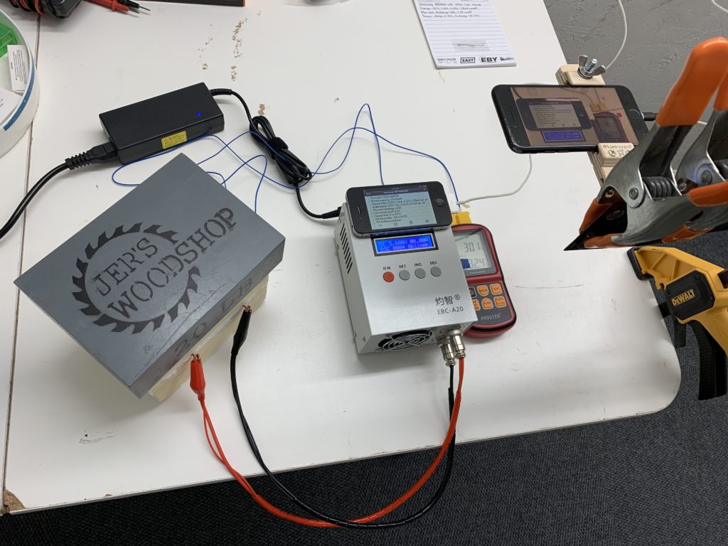
I entered the data from the time-lapse into Google Sheets so I could graph the results of the different cells compared to one another. I’ve made my Google Sheet available for all to view here. If you want to replicate these tests with other cells, send me your results and I’ll add them. Below are screenshots of the most interesting graphs.
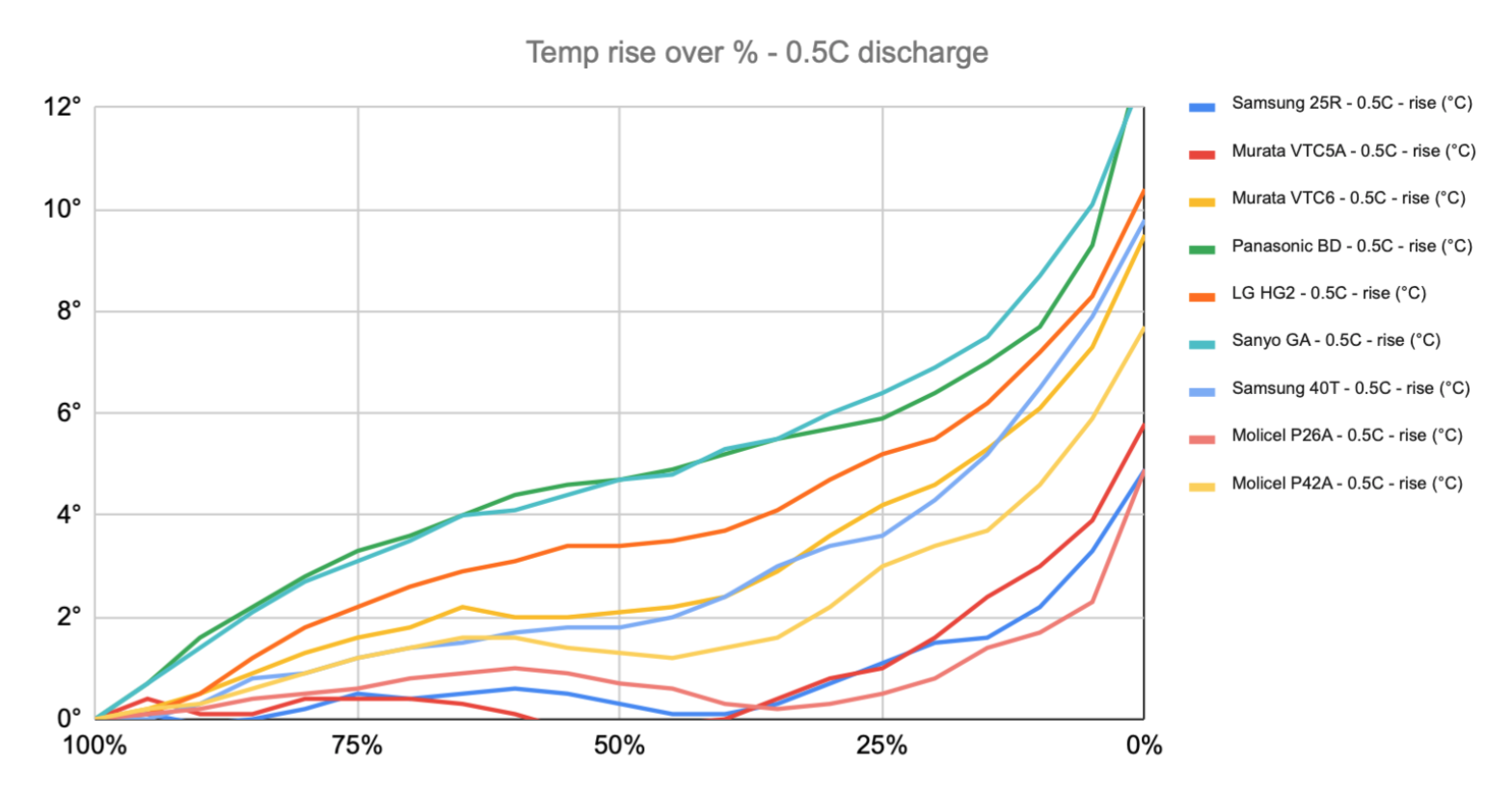
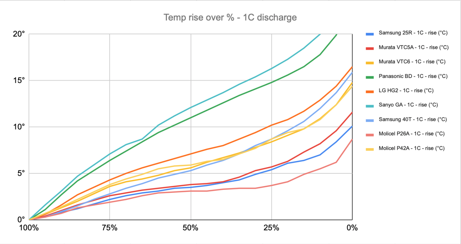
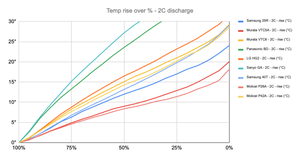
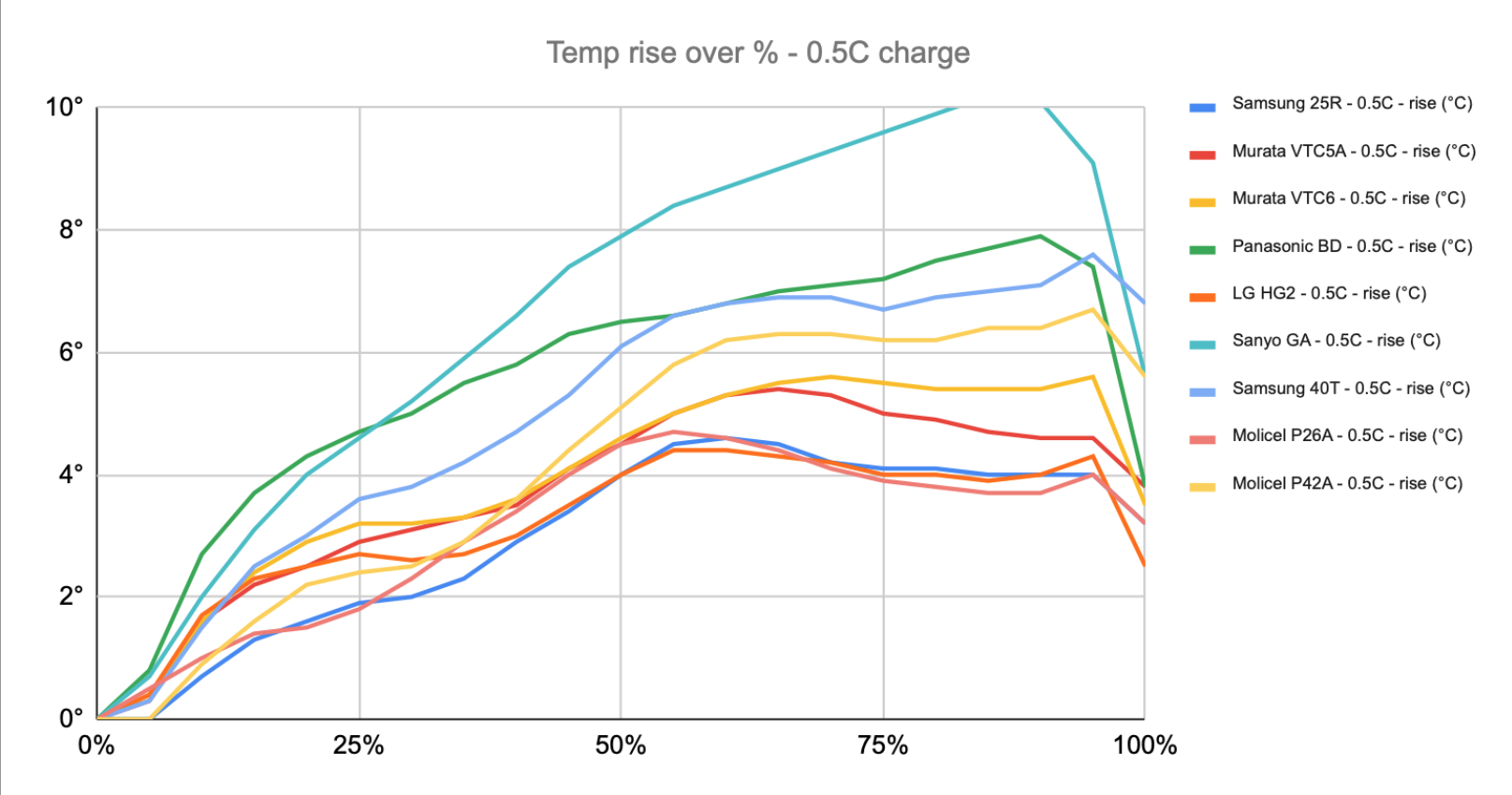
I’m glad I did these tests. They took a long time, but some cells were clearly ruled out, such as the Sanyo GA. It has fantastic energy density, but would have overheated very quickly under the load of powering an ATV. The clear winner is the Molicel P26A, but it is fairly expensive. As of now, when I’m writing this, I’m not sure which cell I’ll end up using, but the Samsung 25R performed very well and is one of the cheapest cells tested, so it’s a likely candidate.
These were my standardized tests that I did for every cell, but I will likely run a few other tests on some of the cells. I’ll publish results here if I do.
